Showing posts with label 3d printer. Show all posts

Saturday, August 6, 2016

Finishing up the iTopie

Having finished building the frame of the iTopie, I began installing all the components of the iTopie one by one.


Y Axis


Followed the steps as given on the Y axis build wiki. I used 35mm M3 screws instead of the 30mm as on the wiki, mostly because my frame is made of 18mm MDF instead of the 16mm MDF used in the wiki's build.
I also needed to grind the ends of the smooth rods as they were a bit longer than 400mm. I then hammered the rods in using a soft hammer. I loved the design of the Y-axis, it is very sturdy, that rod is not going anywhere! Plus, the belt tensioning mechanism is just awesome, requiring you to rotate the motor to provide tension in the belts.

To fix the y-axis stepper to the frame, I used a 20mm and 25mm M3 screws with 3 washers on each screw.

Y Axis fitted to the iTopie frame, before attaching the motor

Picture of the underside of the printer

X Axis and Extruder


I used the X-axis of my existing Prusa Rework printer. iTopie's X axis is compatible all Prusa i3 X-axis. I do not have space to keep two 3d printers, so I will reuse as many parts of my old printer as possible. I just replaced the smooth rods of the X axis with 380mm rods and they aligned perfectly with the smooth rods holes of the z-axis.

I will also be reusing the direct hinged drive extruder with E3D v5 hotend, which is very similar to the following design. I have tried v6 extruders, but have had problems printing PLA with it. So I am sticking to v5 for now.

I have printed the parts for the Wade L3K Extruder. I am waiting on the hobbed bolts from China. Once I receive it, I will replace my hinged extruder with the Wade Extruder. 

If you have iTopie X-Axis parts, then use the X axis build wiki for assembly information.

X-axis from my old printer

The iTopie X-carriage and my old direct hinged X-carriage

Direct hinged extruder, with E3d v5 hotend

Z Axis


Followed the Z axis build wiki again here. I had to hammer the Z rods in place. I was initially apprehensive about the stability of the Z rods as there is no clamping apart form the 18mm support provided by the frame. But it turned out to be very sturdy. Just in case I needed to add external clamping, I had printed the following design, but I found no need to use it.

Reusing my old Z rod holders too.

Heatbed


I used the Mk2 PCB heat bed. I used Kapton tape to add a 3mm cotton insulation to the bottom of the heatbed to decrease heat loss. From top to bottom, my build surface is as follows:

  1. Printbite : Mutley3d guys mentioned that I was their first order from India :)
  2. Glass
  3. MK2 PCB Heatbed
  4. 3mm cotton insulation
  5. Silicone Heat Resistant Pad
I used 35mm M3 screws to mount the heatbed on the Y-carriage.


MK2 Heatbed with 3mm cottom insulation at the bottom.

Silicone Pad
Cross section of my heatbed

PSU Holder


I used a 12V 30A power supply. I decided to mount the PSU on the sides like on standard Prusa's. In iTopie's build wiki they have placed the PSU on the bottom. I designed the PSU holder on OpenSCAD.
I used 3 4x20mm drywall screws to fix the holder to the frame.


RAMPS Holder


I mounted the RAMPS on the left side of the printer. I designed a minimalist RAMPS holder that can be fixed to the iTopie's frame using just one 4x20mm drywall screw.

RAMPS Holder from bottom

RAMPS Holder from side
Holder fitted to the iTopie's frame

Wire organisation : Nylon Sleves, Zip ties and more


Now comes the messy part. The original iTopie has great wire organisation. I couldn't achieve the same level of organisation, but it is better than my older printer. 
I routed the 12V supply cables, Z-axis cables and Y-axis cables through the underside of the frame. I designed and printed about 10 small 1cm x 1.8cm zip tie holders, that I stuck to the frame using 2 sided tapes.
On the side closer to RAMPS, I segregated the cables into 7 parts:
  1. 12V input cable
  2. X Axis stepper and X axis end stop
  3. Y Axis stepper and Y axis end stop
  4. Z Axis steppers and Z axis end stop
  5. Heatbed cables i.e. thermistor and heater cables 
  6. Hotend cables i.e. thermistor and heater block cables
  7. Extruder Motor and hotend fan cables

Printer's underside from right

Printer's underside from left


Some wire segregations can be seen here

The zip-tie holders attached to the frame using a 2 sided tape


Extruder and Hotend cables

Not very pretty, but does the job of organising the cables.

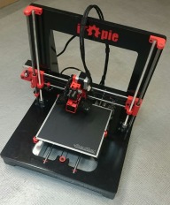
My iTopie : All installed and ready to print


Finally finished it!!

An up top view of my "new" 3d-printer

First non-caliberation print. I am happy with the result as I haven't tuned the printer at all.


COMING SOON : Bill of Materials and other helpful resources to help anyone in India source parts for an iTopie.


Saturday, July 30, 2016

Building the frame : iTopie

Full 2 weeks have passed since I received the frame from the CNC shop. Now, I finally start on my iTopie build. Before I could begin, I needed to sand all the notches and pegs to make them fit easily. To avoid all this sanding, Chandrakanth, the CNC shop owner, suggested I make the pegs 0.5mm thinner next time. Hmm..

The brilliant build guide on Reprap' wiki shows how to assemble the whole frame, so I will not be repeating all the steps again. Follow this link to go wiki's build. I was unable to find the 3.5x40mm drywall screws, so I used 3.5mmx38mm drywall screws instead.

My current 3D printer moves/vibrates too much while printing to provide high quality intricate prints. One of the reasons I had chosen to build an iTopie, was due to the rigidity of its frame. This was my first time build a 3D printer form scratch, I really wanted all the pieces to be square and not mess anything up. I used my set squares constantly, to make sure every this is at right angles to each other. I am really happy with the results. Here are some of the pics of the final frame assembly and painting:

The frame of the my new iTopie, which will cannibalize the printer om the left. RepCanb rather than RepRap :P

Every thing is exactly as it should be. The white patches are from the putty I used.

After the first cost of primer. I put together a make shift painting "booth" using a large amazon box I had lying in the house.

A bit of sanding. I sanded the whole frame after each coat of the primer to get an even shine.

After another coat of primer, sanding and two coats of smooth gloss paint. Has my finger prints in some places, I guess its personalized now.


The cost for this build till now has been around Rs 3500, majority of that being:
  1. MDF : Rs 800
  2. CNC costs : Rs 1500
I have mentioned where I got the frame cut in this blog post. I used only a small amount of the following items, they will be useful around the house and in other projects. So I am not counting their full cost to the build's cost.
  1. 3.5x38mm drywall screw (Rs 260) : ebay.in
  2. Black Primer Spray Paint (Rs 540) : amazon.in
  3. Black Primer Glossy Paint (Rs 540) : amazon.in
  4. Fevicol SH 0.5kg (Rs 125) : available in most hardware stores
  5. Asian Paints Dent Filler 1kg (Rs 150) : available in most hardware stores
Final Part : Finishing the iTopie


Wednesday, July 6, 2016

Build a iTopie 3d Printer in India from scratch

Why a 3d Printer?


3D Printing is awesome. Thingiverse, Youmagine and yeggi are great sites where many 3d models are available for free and if you have a 3D printer you can make these parts at home. Have a look there and just glimpse the possibilities.

3D Printing is a challenging and has a steep learning curve. I bought my first 3D printer 4 months ago. It is a Prusa i3 Rework. Prusa i3 is the the most widely used DIY printer out there, and the most likely printer to be a bought by someone who is trying to jump into 3D printing.

3D Printers are not "THAT" expensive anymore. In fact, in this build I will try to remain below the Rs 25,000.

So, if want the power to create 3D objects on your desktop then start your journey on the Third industrial revolution.
My Prusa i3 Rework. Just an example of the things that you can print. At the back the translucent white box is converted into a custom airtight filament holder for my 3d Printer using my 3d Printer to build its parts. RepRap indeed!!

Why iTopie?


3d Printing requires precision and repeat-ability. Usually, the cheap DIY printers are made of acrylic frames, which are prone to bending under stress and cracks. My current printer has an 8mm acrylic frame, which provides great stability. But acrylic is prone to bending under stress and cracking.  In hindsight, because Prusa i3 was my first DIY 3d printer, I tightened the screws tighter than they were meant to be tightened, resulting in cracks. Now, the stress of printing is slowly making the cracks wider :(

Which brings me to iTopie. iTopie's unique frame is made entirely of  MDF.  Medium Density Fiber is denser than plywood and has high structural integrity, which means it doesn't bend easily. MDF boards are widely available in India, in fact some of your  furniture might be made of MDF. Another benefit is the quicker assembly time compared to other Prusa i3 variants.

This means iTopie can theoretically print at a better quality at higher speeds.Which sounds awesome, considering how slow the whole process can be.

Getting Started


Build Manual and Parts List

In these series of blogs, I plan to make a iTopie printer, from scratch using components easily available in India. The printer itself is very easy to build. All you need is some Fevicol SR, A Drill machine (with 3mm drill bit), some drywall screws, a can of spray etc. I have ordered parts from the Bill of Materials/Parts List,

I will share my own BOM in the coming posts. Most of the parts have been ordered online from Indian stores and remaining from Alibaba Express. The aim is to make a Rs 25000 printer.

I will follow the RepRapWiki's Build Manual for iTopie (here) . I plan to document the variations in the original Build Manual due to lack of compenents in India or in generally to me. Partial list of differences are following, more will be documented as they arise:
  1. I cut the frame using 18mm MDF, instead of 16mm used in the original design. Its was easy to generate the new DXF files for 18mm MDF and 6mm pocket size. I just followed the instructions given on the Wiki. This was because 18mm frames very easily available in India. I used Greenply weather proof MDF. 
  2. Using RAMPS+ARDUINO MEGA electronics instead of Smoothieware board
  3. Maybe, will get an enclosure for the printer. (??)
Getting the iTopie Frame CNCed

Before I could do anything,  I had to get the MDF routed to make the iTopie frame.You need access to a CNC machine to be able to do that. But don't worry, many Indian cities have facilities for CNC routing. Since, I live in Bangalore, I looked around for a local CNC Shop and found this site. This woodwork shop is run by a great guy, Chandrakanth. I visited their shop to discuss the design 3 days back and I have already received pics of the finished frames. It has all been very professional and satisfying.
A freshly minted iTopie frame in Bangalore. Cant wait to receive it from the workshop.
Follow the build on this blog post.